TrafficXHub™ has 2 main components: the sensor and the antennas.
Sensor #
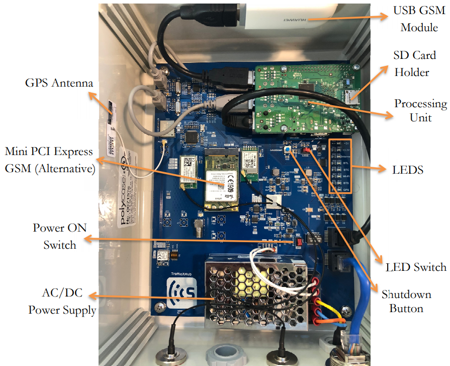
The sensor is the main component of the whole system and is responsible for the following tasks: Wi-Fi and Bluetooth scanning, data storage, sensor status monitoring, LED control, and communication via Wi-Fi, Ethernet, or Cellular modem. The image below illustrates the sensor mainboard’s components.
Power Supply #
The sensor can be powered through 3 different sources: Power-over-Ethernet (PoE), AC, or 12V Solar Panel/Battery.
Power Switch #
The power switch powers the sensor ON and OFF when the AC or Solar Panel Battery power sources are used. The PoE does not have any power ON switch. Once the sensor is powered ON, the processing unit starts the scanners and other processes until the sensor is fully functional and connected to the SMATS server.
LEDs #
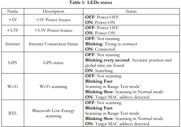
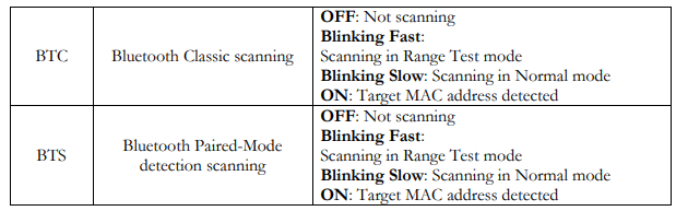
TrafficXHub™ unit has eight LEDs to show the status of the sensor’s power supply, internet connection, GPS, and scanners. Turn ON/OFF the status LEDs for power saving in solar-powered cases and range testing mode. Table 1 presents the description of each led and their status definition:
Ethernet and Antenna Connections #
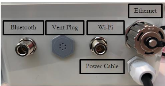
On the bottom side of the sensor, an Ethernet and two N-Type RF connectors are available, as seen in the image below. The Ethernet connector can be used for PC connection to configure the sensor or for LAN/PoE connection. The N-Type connectors are used to connect Wi-Fi and Bluetooth antennas to the sensor.
External Antennas #
TrafficXHub™ can detect Bluetooth Classic in Discovery, Bluetooth Connected, Bluetooth Low-Energy (LE) Discovery, and Wi-Fi activated devices. Two RF-2.4GHz antennas are to be attached to the bottom of the sensor where N-type connectors are located.