Connecting to the Web UI #
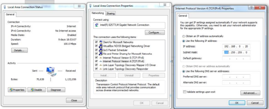
The sensor is featured with a comprehensive local web user interface that can be used to configure the sensor, download the data, and conduct other various tasks. There are two ways to connect to the Web UI: through static IP or DHCP. In the former case, you need to connect the sensor to a PC using an Ethernet cable. Change the PC Ethernet setting to the following static IP and Subnet mask (See image below):
IP: 192.168.0.20
Subnet mask: 255.255.255.0
Turn on the sensor. Open an Internet browser (Chrome or Mozilla) and type “192.168.0.22” in the browsers’ URL bar and press Enter. The sensor Web UI status page should appear shortly.
In the latter Case (DHCP), an office router is required which assigns an IP address to the sensor once it’s connected to the router through an Ethernet cable. This new IP address can be found by checking the device list of the router or using
http://raspberrypi.local/ as the host name. Once IP is found, the procedure is the same as in the former case, which includes opening an Internet browser, typing in the assigned IP address in the URL bar, and pressing Enter to bring up the web UI page. To access all the configuration menus login to the interface using “admin” as the username and password.
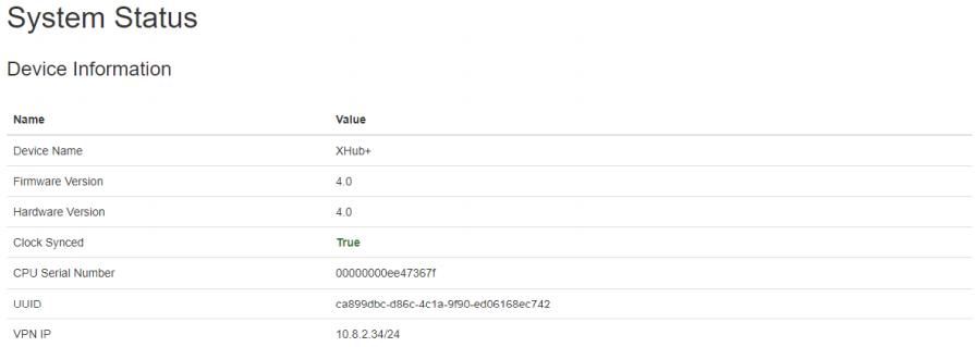
System Status #
The system status page shows information about the sensor, running processes, and recent saved data. The device information section includes device hardware and firmware versions, serial number, and the sensors’ clock sync status. The latter is an important flag showing whether the clock has been synced via GPS or the Internet since the sensor was powered on (See image below, “True” status).
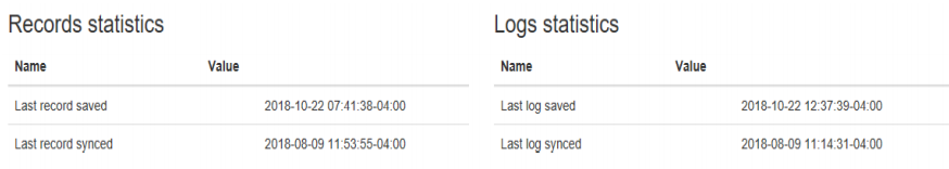
The records (Wi-Fi and Bluetooth MAC addresses, RSSI, and Detection Time) and logs statistics provide information about the last record and system log saved on the sensor SD card.
Note: The records and logs are not saved to the SD card if the sensor clock is not synced
The Monitor section provides information about the sensor connection status, GPS, SD card usage, and temperature and humidity sensor.
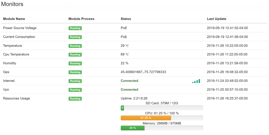
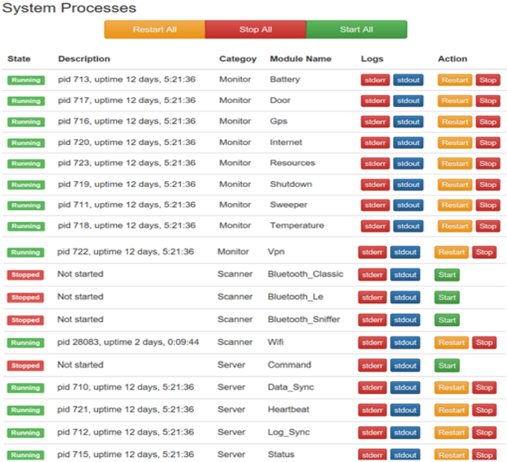
The System Processes status includes the list of processes and their status, i.e. running, stopped, and exited. The output of each process can be monitored by clicking on “stdout” and “stderr” buttons.
Basic Configurations #
The Basic Configurations tab provides options to change the sensor’s settings related to the scanner, connection to SMATS iNode™ analytics server, and internet connection.
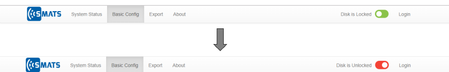
Important: Before making any changes to the configurations and press save button, ensure that the Disk is unlocked.
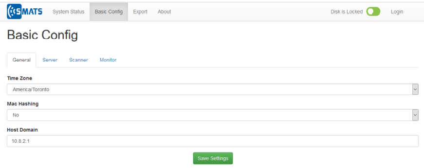
General #
In the Basic tab (Seen in the image below), parameters including the sensor time zone, MAC Hashing, and Host Domain. Setting the MAC Hashing to “Yes” will result in storing the modified form of the detected MAC addresses to avoid any privacy issues. The time zone is the local time zone of the location where the data is collected. The host domain is the endpoint connection to the iNode™ data analytics server.
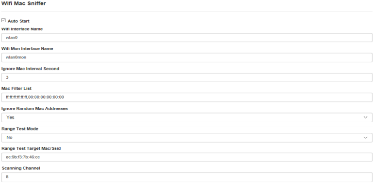
Scanner #
The scanner’s settings tab is used to change the configurations of Wi-Fi and Bluetooth scanners. The “Auto Start”, when checked off, determines if a scanner starts up when the sensor is boot up. In order to identify if a known Wi-Fi or Bluetooth MAC address is detected during the scanning process, set the “Range Test Mode” to “Yes” and enter the 6 byte MAC addresses with the format shown in the image below. In this mode the scanner’s LED blink fast and once the target MAC address is detected the LED becomes solid. To re-start the LED status, turn off and on the LED switch. This feature of the application can be used for testing the sensor’s detection range. This can be done by beginning to approach the sensor from a far distance with a known device, such as a cellphone with Bluetooth in discovery mode (must go to the setting menu and then Bluetooth), or with Wi-Fi turned on and screen unlocked until the MAC addresses are detected. At that point, the distance between you and the sensor is the maximum detection range for a typical test device (such as a cell phone) and the surrounding setting.
Note: For Bluetooth Paired Mode detection only enter the last 3 bytes of the MAC address (not the complete address). For instance, if your device’s Bluetooth MAC address is AC:EE:9E:24:6C:64 only enter 246c64.
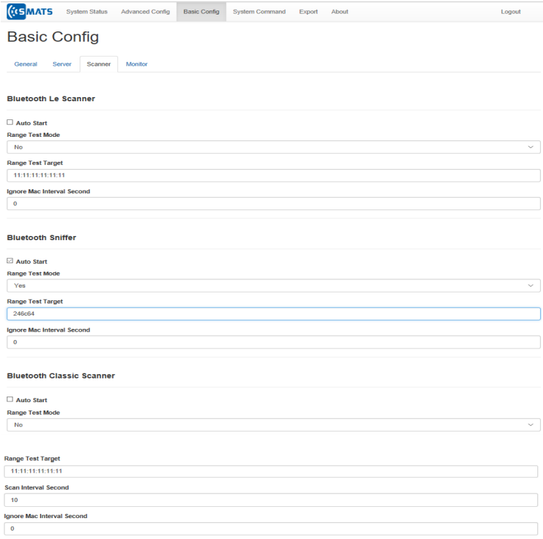
“Ignore MAC Interval” (in seconds) is a time interval during which a repeated MAC address will not be recorded as a new detection. This helps to save memory space.
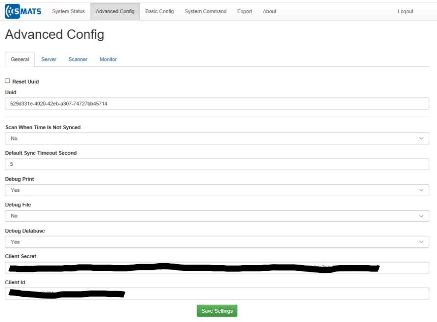
Advanced Configurations #
General #
In this Advance Tab (see image below), the most important parameter is UUID. The UUID is a unique identification of the sensor by which it establishes a connection to iNode™. If the sensor retires from one project and wants to be moved to another project/location, this UUID number must be reset. By doing so, iNode™ would see it as a new device and create a new table for data collection at the server end.
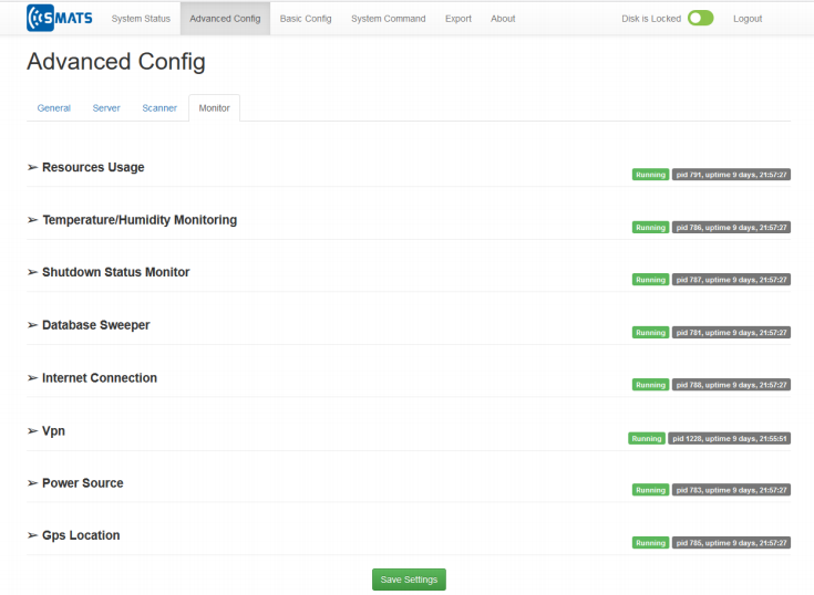
Monitor #
Monitor tab is used for setting advanced configuration for Internet Connection, VPN, Database Sweeper and so on. This section is only for advanced users.
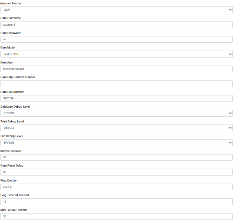
Internet Connection (GSM Settings) #
An Internet connection is required for real-time communication of the sensor to the iNode™ server or syncing the sensor clock where GPS signal reception is poor (i.e. indoor locations). Settings for the Internet source (cellular, Wi-Fi, or Ethernet) can be configured under “Internet connection” tab. The image below shows the settings for the Internet connection when the source is GSM. A sensor is shipped with a compatible GSM model to your cellular network provider. If the SIM card is not provided by SMATS, you need to put a Micro size SIM card and know and set the SIM card APN in the configuration menu.
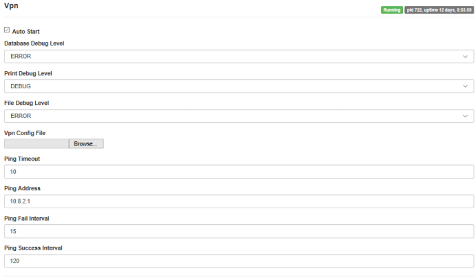
VPN Settings #
In order to have remote access to the sensors, a VPN connection needs to be established between the sensor and the iNode™ server. Under the Monitor tab in the advanced configuration settings, a “VPN config” client file can be uploaded. This comes pre-loaded in most of the cases. The rest of the VPN settings are shown below.
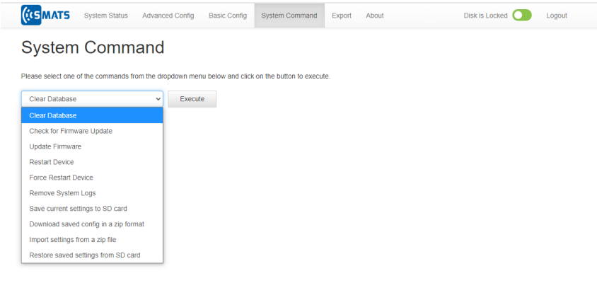
System Command #
The system command menu can be used to:
1- Clear (sensor’s local) database. This will empty the SD card MAC records
memory.
2- Check for firmware update
3- Update sensors’ firmware (Internet connection is required).
4- Restart device
5- Remove system logs
6- Save current local setting
7- Export current settings as a zip file
8- Import settings as a zip file
9- Restore last local settings
Note: The current configurations are set to default after a firmware upgrade and need to be restored after.
Data Export #
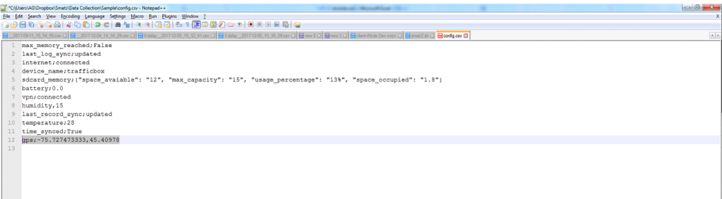
The collected MAC address records can be exported to a CSV file using the Export menu, seen in the image below:
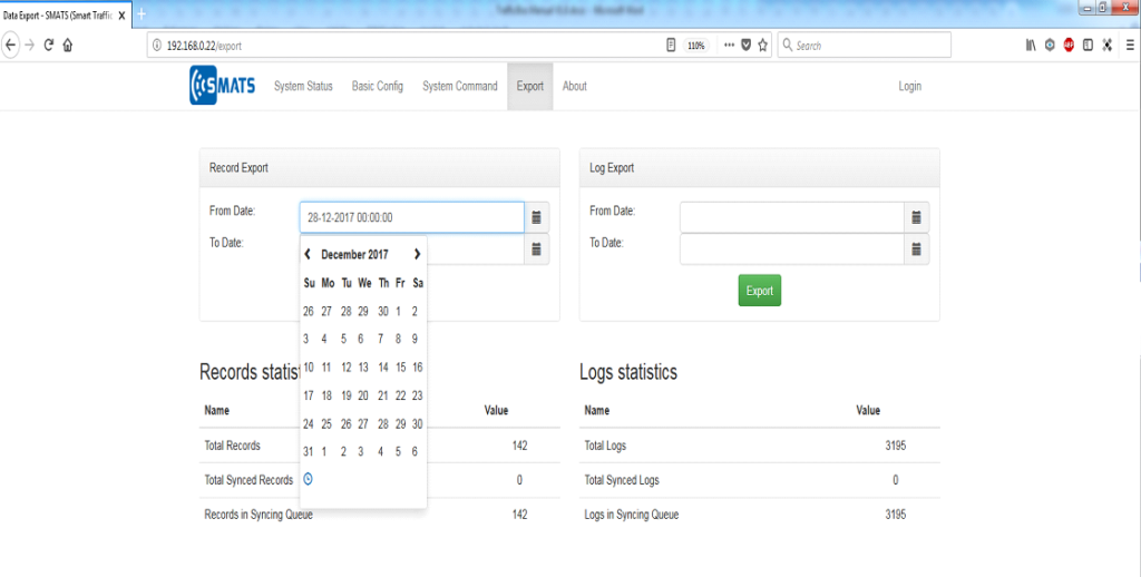
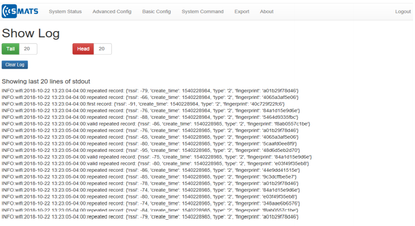
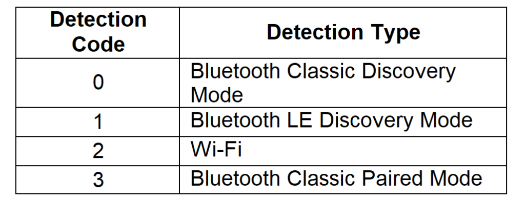
The data export creates two output files: “records.csv” and “config.csv”. The records.csv file includes fingerprint (MAC address), detection type (e.g. Bluetooth vs. Wi-Fi), detection signal strength (RSSI), and detection time (create_time). The image below illustrates the contents of the records.csv file.

The detection types are coded as follow: MAC address detection codes
The “config.csv” file includes the information of the latest status of the sensor, such as SD card usage and last location GPS coordinates (see image below).